From the Electrostatics
80. Measuring potential differences
A device called an voltmeter is used to measure the potential difference. Figure 1 shows one of the simplest voltmeter. The main part of it is a light aluminium arrow fixed on a metal rod in a horizontal axis. The arrow can rotate around this axis. Before the measurement begins, the arrow is vertical because its center of gravity is below the axis. The rod and arrow are placed in a metal frame, isolated from the rod by an ebonite plug. An inspection window is provided to observe the arrow. The voltmeter looks like an electroscope, but differs from it in that it has a metal frame.
To measure the potential difference between two conductors, one of them is connected to the rod of the voltmeter and the other to its frame. (If you want to measure the body's potential relative to the Earth, the body is connected to the rod by a conductor, and frame is grounded.) Then a potential difference is established between the frame and the rod, which has to be measured. For a given potential difference the field inside the voltmeter is clearly defined, because the shape of the frame of the voltmeter is the same. Distribution of the field inside the voltmeter defines forces acting on the arrow. To be able to judge the quantity of the potential difference from the indications of the arrow, the device should be configured. For this purpose it is necessary to find, what angles of deviation of the arrow correspond to known values of voltage between charged conductors.
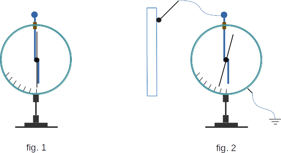
Using the voltmeter, it is easy to check from experiment that all points of the conductor have the same potential relative to the Earth. For this purpose, it is enough to connect different parts of the conductor to the rod of the voltmeter, whose frame is grounded (fig. 2). Readings of the voltmeter will not change in this case.