From the Direct electric current
98. Ohm's law for a circuit section containing EMF
Let's now consider a circuit section containing a galvanic element or battery, that is, a section on which EMF operates equal to \(\mathcal{E}\,.\) This section is, for example, section \(AB\) in figure 1. The potential difference at its ends is \(\Delta{V} \,= \,V_a \,- \,V_b\,\). Let us define this by the EMF of section \(\mathcal{E}\,,\) its resistance \(r\), and electric current force \(I.\) It is obvious that \(V_a \,> \,V_b\,,\) if point \(A\) is at the positive pole of the element. Applying Ohm's law \((9-8)\) for a closed circuit, we get
\( \mathcal{E} \,= \,I\,R \,+ \,I\,r \) (9-9)
On the other hand, applying the Ohm's law \((9-4)\) for a section of the circuit which does not contain EMF but has only resistance \(R\) (this section is also between points \(A\) and \(B\), but in the bottom part of fig. 1), we can write
\( \Delta{V_{ab}} \,= \,I\,R \) (9-10)
Replacing \(IR\) in equation \((9-9)\) with \(\Delta{V_{ab}}\) from equation \((9-10)\), we obtain
\( \Delta{V_{ab}} \,= \mathcal{E} \,- \,I\,r\) (9-11)
This is Ohm's law for the part of the circuit containing EMF. The potential difference at the ends of the circuit is equal to the segment EMF minus the product of current force per segment resistance. (The value of \(Ir\) is sometimes called the voltage drop at resistance \(r.\))
When the circuit is open \(I \,= \,0\) then
\( \mathcal{E} \,= \,\Delta{V_{ab}}\)
Therefore, the EMF of an element is equal to the potential difference between its poles when the circuit is open.
Ohm's law in the form \((9-11)\) refers to the case when the electric current inside the element is directed from the negative pole to the positive pole, i.e. in the direction of the field strength of external forces. (For short, let us say that the electric current is directed along EMF.) Another case is possible, when the electric current in the element is directed from the positive pole to the negative pole (i.e. against EMF) and the external forces perform the negative work. This direction has an electric current, particularly when charging the battery. If, in the circuit section shown in figure 2, the electric current flows in the direction of the arrow, it flows through the \(\mathcal{E_2}\) element just against the EMF.
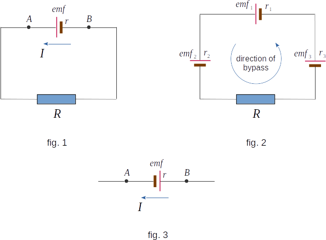
Let's consider separately the section of the circuit \(AB,\) where the electric current is directed against EMF (fig. 3). This section differs from the section \(AB\) shown in fig. 1 only by the fact that the galvanic element "plus" and "minus" are rearranged in places. This change in the polarity of the element corresponds to a change in the EMF sign in the equity \((9-11)\). Hence, in this case
\( \Delta{V_{ab}} \,= \,-\mathcal{E} \,- \,I\,r\) (9-12)
By changing the signs in the left and right parts of the equity \((9-12),\) we get
\( \Delta{V_{ba}} \,= \,V_b \,- \,V_a \,= \,\mathcal{E} \,+ \,I\,r\) (9-13)
The potential difference at the ends of the circuit section is equal to the electromotive force plus the product of the electric current force on the internal resistance of the element \(r\) (voltage drop at resistance \(r\)).
Both equations \((9-11)\) and \((9-13)\) can be combined into one if the potential of the positive pole of the source EMF is marked \(V_{\oplus}\) and the negative pole is marked \(V_{\ominus}\). Then
\( V_{\oplus} \,- \,V_{\ominus} \,= \,\mathcal{E} \,\mp \,I\,r\) (9-14)
The "minus" sign refers to the case when the electric current is directed along EMF and the "plus" sign refers to the case when the direction of the electric current is opposite to the direction of the field strength of external forces.