From the Electromagnetic induction
133. The law of electromagnetic induction
Let's formulate the law of electromagnetic induction quantitatively. Experiments show that the induction current \(I_i\) in the conducting circuit is proportional to the speed of change in the number of magnetic induction lines \(\overrightarrow{B}\) penetrating the area limited by this circuit. After introducing the concept of magnetic flux \(\Phi_B\), we can clarify this statement: the induction current in the circuit is proportional to the speed of change of magnetic flux through the area bounded by the circuit. If, in a very short time \(\Delta{t}\), the magnetic flux changes by the value \(\Delta\Phi_B\), the speed of change \(\Phi_B\) is equal to the ratio \(~ \frac{\Delta\Phi_B}{\Delta{t}}\).
Consequently, it can be argued that
\( I_i \,\sim \,\frac{\Delta\Phi_B}{\Delta{t}} \)
Obviously, the induction current depends not only on the ratio \(~ \frac{\Delta\Phi_B}{\Delta{t}}\), but also on the property of the conductor itself, i.e. its resistance. In order that the law of electromagnetic induction does not contain a dependence on the properties of the conductor, it is necessary to formulate it not for the induction current. We know that an electric current is generated in a circuit when there is an electromotive force. Consequently, when the magnetic flux changes through the area bounded by the circuit, EMF appears in it. This EMF is called the EMF induction. We will denote it by \(\Large{\varepsilon{_i}}\).
Knowing the current \(I_i\) and resistance of the circuit, you can use Ohm's law to find \(\Large{\varepsilon{_i}}\). Experiments show that currents in different conductors at the same speed of change of magnetic flux are different in magnitude only because of different resistance of the conductors. This makes it possible to formulate the law of electromagnetic induction in the following way. EMF induction in a closed circuit is equal in magnitude to the speed of change of magnetic flux through the area limited by the circuit
\( |\Large{\varepsilon}\small{_i}| \,= \,|\frac{\Delta\Phi_B}{\Delta{t}}| \)
Let us now see how the law of electromagnetic induction selects the direction of induction current (or the EMF sign of induction) according to the Lenz's law.
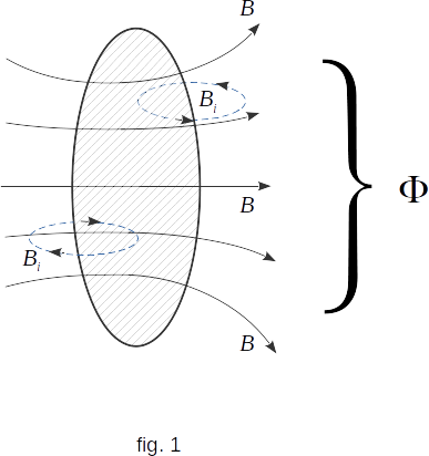
Figure 1 shows a circular circuit. Let us consider the current in the loop (and therefore EMF) positive if the direction of the magnetic field \(\overrightarrow{B_i}\) of the induction current inside the loop coincides with the direction of the magnetic field \(\overrightarrow{B}\), the change in which generates the induction current. According to the Lenz's law such coincidence of directions of magnetic fields \(\overrightarrow{B_i}\) and \(\overrightarrow{B}\) will be if the magnetic flux \(\Phi_B\), change of which generates the induction current, decreases, i.e. if \(~ \Delta{\Phi_B} < 0 ~\) and \(~ \frac{\Delta\Phi_B}{\Delta{t}} < 0\).
In order for the EMF induction to be positive, as we have agreed, the law of electromagnetic induction must have a minus sign